Saturday 31 March 2018

688 Stormtrooper Minifigures - behind the scenes...


688 Stormtroopers combines two python scripts that I’ve been working on for quite a while. The first is a reasonably simple mosaic script that I wrote to create Lego mosaics using single coloured studs. The script analyses the pixels in an image the matches the pixel colour to a nearest Lego colour. There are quite a few Lego mosaic building tools out there now and there is even one with a web interface to build your own mosaic.

Here's my version of a Lego mosaic script....

import random,sys,math
from ldraw.colours import *
from ldraw.figure import *
from ldraw.pieces import Group, Piece
from PIL import Image

#From http://stackoverflow.com/questions/34366981/python-pil-finding-nearest-color-rounding-colors
def distance(c1, c2): # Work out the nearest colour 
    (r1,g1,b1) = c1
    (r2,g2,b2) = c2
    return math.sqrt((r1 - r2)**2 + (g1 - g2) ** 2 + (b1 - b2) **2)

#Open the image
im = Image.open('flower.bmp').convert('RGB')
#Get the pixel data
pixels = list(im.getdata())
width, height = im.size
pixels = [pixels[i * width:(i + 1) * width] for i in xrange(height)]
rgbPixels = im.load()

#print pixels #Used for checking

print "Creating Lego..."
print "Width...", width, "  Height...", height
onexonexone = Group(Vector(0, 0, 0), Identity())

#Set up the LDraw file
LDrawFile = open('picture.ldr', 'w')
LDrawFile.write('0 // Mosiac Maker Colour - Neil Marsden'+'\n')

#Set Up the Lego Colour Dictionary
#rgb_code_dictionary = {(27,42,53):26, (242,243,243):1, (163,162,165):194}
#(255, 217, 168):RED,(196, 0, 255):FLESH,(30, 0, 255):PURPLE
#rgb_code_dictionary = {(0,0,0):0, (87,87,87):8, (110,110,110):7, (190,190,190):503, (255,255,255):15} #GreyScaleOnly - Black,DarkGrey,Grey,LightGrey,White
rgb_code_dictionary = {(252, 252, 252): 15, (199, 200, 223): 20, (84, 163, 173): 11, (248, 227, 148): 18, (239, 203, 54):14, (153, 159, 155): 7, (87, 56, 39): 6, (198, 111, 158):5, (185, 230, 11): 27, (0, 84, 189): 1, (239, 111, 93): 12, (37, 121, 61): 2, (5, 19, 29): 0, (74, 157, 73): 10, (144, 56, 119): 26, (249, 149, 170): 13, (178,208, 224): 9, (128, 0, 122): 22, (113, 14, 15): 320, (167, 84, 0): 484, (0, 129, 141): 3, (199, 26, 9): 4, (108, 109, 91): 8, (192, 216, 182): 17, (225, 203, 156): 19, (32, 49, 174): 23,(100, 73, 61): 19,(86, 59, 43): 92,(116, 66, 4): 25}

#set start co-ordinates
x=0
y=-20
z=0
rot = 0
counter = 0
col = 0
#Work through each row of pixels in the image
for i,row in enumerate(pixels): 
#print row
for j,pixel in enumerate(row): # Then work through each pixel in the row
#Get the  RGBA value (colour) of each pixel

col = rgbPixels[j,i]
#Check the pixel colour with the Lego dictionary colours
point = col
colors = list(rgb_code_dictionary.keys())
closest_colors = sorted(colors, key=lambda color: distance(color, point))
closest_color = closest_colors[0]
code = rgb_code_dictionary[closest_color]


#set the Lego colour to the colour code
col = int(code)
#Up the counter and increment the brick position

counter += 1
y += 20
#Create a new row when the counter is greater than the width of the image
if counter > width: 
#print "new row"
LDrawFile.write('0 // NEW ROW '+ str(x/20) + '\n')
x += 20
y = 0
counter = 1

#print i,j,x,y,col,code #Used for checking
#Write the brick to the file
#print "Wrting brick here..."
LDrawFile.write(str(Piece(Colour(col), Vector(x, z, y), Identity().rotate(rot, YAxis), "3024", onexonexone))+'\n')

It's worth remembering that a 50x50 pixel images will be 2500 pixels = 2500 studs so you can very quickly end up with a lot of Lego pieces!   Here's and example of an original image and the resulting mosaic.


My second script was more complex, and uses a library folder of different ldraw models to create a much larger and more complex model (and I also use Tribex's libldrparser.py to parse my initial ldraw library models). I’m a bit of a hack and mash programmer, so I hack bits of code from the internet and mash them all together to get the code to do what I want, I can usually get the output I'm after but sometimes I’m not entirely sure what’s going on!  My early tests used some simple "city" based micro models


So my script reads and stores the data about each piece in the mini-model in the library folder and then randomly moves (on a 4x4 grid) and rotates each library model to create a larger model. So this "city" is created using 11 mini-models.


So the final model, whilst looking complex is built based on the library of mini-models provided.   Here's a link to 5 random city models - the script creates one of these "cites" in less than 1 minute


Or this “library” of flamingos...


I realized that a minifigure is just a library of parts (legs,torso,arms,hands,head etc) and if I used the mosiac image analysis script and combined it with the my ldraw model placement and rotation script that I should be able to create 688 Stormtroopers.  Instead of placing a single stud I could place and rotate a minifigure. In the process I discovered that there was a rounding error in the rotation element of my mini model placement script and I had to fix all the stormtrooper hands manually in Excel - painful! I don’t really want to put my script up till it’s working properly so I’m going to try to fix the rotation error but my understanding of rotation matrices and euler angles is not great and it might take a bit longer to fix.


Tuesday 27 March 2018

Creating Building Instruction Documents For A LEGO Remote Controlled Car (PART 1)

I've been working on a project to allow students to create a simple remote controlled (RC) wheeled car that would have some ability to drive and steer. The age of the students varies from 8-12 years and not all of them are that familiar with Lego.  So I needed to keep the model simple and functional.  I also have a limited amount of time with the group of students so I would need to provide a part built model to which they could add the main components, like motors, battery pack, infra-red receiver etc.   The main purpose of the event is not to build the RC cars but to drive them round and bash them up (Robot Wars style)


Although the basic car is fairly simple I would still need to provide some instructions for assembling the part built components.  I modeled the car in Roland Melkert's LDCAD (http://www.melkert.net/LDCad/download).  Whilst I could build the model in Lego Digitial Designer (LDD) I have no control over the resulting instructions that get created and there is no option to generate partial instructions.  Stud.io, I discovered, lacks many of the power function motors that I wanted to use in my model, so that was a non-starter.  LDCAD is quirky but it is a highly competent Lego modeler and if you are prepared to put the time in,  it can create some lovely models some of which, I've not been able to create in any other package (that's not to say that other packages can't do the things LDCAD can, it's just I haven't figured out how!).


There are a number of tutorials on the LDCAD website which provide a good introduction to how LDCAD works and I found I needed to work through the tutorials in order to really understand how the various elements of LDCAD functioned.  Having completed the tutorials, building my RC car was relatively straight forwards.  What I needed to do now was to create the building instructions...


Tuesday 20 March 2018

MODO and LDRAW (Part 3)

One of the problems that I discovered with using MODO command line was that there appear to be a number of commands that don't seem to work.  They work in the GUI version of MODO but when you execute the commands in the command line, MODO_CL responds that it has executed the command but doesn't actually do anything - this is frustrating especially when you're just starting using the scripting tools and you've only got a limited trial period to figure things out.  Some of these commands play a key role in framing the model in camera and then rendering the resulting output.

These commands include...

viewport.fitSelected
camera.fit true true
camera.syncView
render.syncView

All the above are useful for trying to frame a model in camera automatically.  By the time I realised these commands didn't work I'd lost a couple of days.  So I needed a mechanism of figuring out how to get the bounding box data for a model in MODO.  There are some useful leads in The Foundry community pages but needless to say not that many trying to frame LEGO models from the command line.

In the end I created the following python script that I could call from MODO_CL and it would give me the bounding box (both local and world) dimensions for all the assets (bricks) in the model.

#C:\python27\python.exe

# From MODO_CL prompt execute the following...
#Open your LDR file...
#scene.open "C:\Users\Neil\Google Drive\modoscript\lighthouse2.ldr"
#Call this script!
#script.implicit "C:\Users\Neil\AppData\Roaming\Luxology\BoundingBox.py"

import lx

selLayerIDs = []

selLayers = lx.evalN("query layerservice layers ? all")
print selLayers
for layer in selLayers:
    #this will also 'select' the layer for the layerservice
    layerID = lx.eval1('query layerservice layer.ID ? %s' % layer)
    selLayerIDs.append(layerID)
print "Layer Name", selLayerIDs

#select items
for mesh in selLayerIDs:
    lx.eval('select.subItem %s add' % mesh)
    print mesh
    lbounds = lx.eval('query layerservice layer.bounds ? %s' % mesh)
    wbounds = lx.eval('query layerservice layer.wbounds ? %s' % mesh)
    print lbounds
    print wbounds

It's looks simple but the problems I had in getting this script to run from the command line were considerable - some python scripts ran, some didn't - I never figured out why.  Errors from both Python and MODO_CL were difficult to untangle and isolating the data from individual bricks, which should have been easy, turned out to be anything but! 


I ended up analyzing the output in Excel because I was running out time with my trial version and I was never really able to isolate how to calculate the camera framing from the bounding box information - it should be easy but in the time I had available it defeated me.

I've included it here in case anyone else works with MODO_CL, LEGO, LDRAW and Python - this may help you get started.

My trial of MODO has now ended so I need to wait for MODO V12 which The Foundry have said should be out shortly before I can investigate MODO any more.

Sunday 18 March 2018

Brick Battling Bots - Round 1!

We ran our first Brick Battling Bots session last week - great fun and thanks to all the scouts who took part to build and battle their 'bots.  Congratulations to the RED team for sealing victory in the final bout - A few photos of the event below...


After the event we made some changes to the basic design on the 'bot to make it quicker and stronger - we also discovered that when you have 8 robots managing the remotes becomes quite important.  We're looking forward to our next event in April.

Tuesday 13 March 2018

MODO and LDRAW (Part 2)

Modo can create beautifully rendered images of Lego with just the default lighting setup


Previously I'd spent quite a bit of time writing command line scripts for POV-Ray to render LDRAW models.  Using a combination of Python and other tools I can directly access all the features of POV-Ray (well, the ones that I understand!) via a scripting interface.  Scripting allows me to rapidly create multiple rendered views of a model so that I can quickly see how the lighting and rendering effects different parts of the model in question.  I used Lars Hassings lovely little utility L3P (http://www.hassings.dk/l3/l3p.html) to frame the model for subsequent POV-Ray renders.  Part of a simple POV-Ray scripted turnaround is featured in the images below.


MODO also has a command line interface (modo_cl.exe - modo command line) so the ability to script the output of MODO seemed a distinct possibility - the reality turned out to be a lot more complex!

MODO does have a complete command line interface but picking my way through various documents, snippets and scripts available online was hard work, and it often seemed that the complex things were easy and the easy stuff was complex!  For a number of reasons I wanted to script the complete pipeline from LDR file to rendered image, so put simply, initially I needed to... 

Import an LDR file
Frame the camera on the model
Render the image 
Save the rendered image to disk
Save the resulting file as a native MODO file

From the command line MODO has a medley of scene, layers, items and other functions to control and manipulate.  When you only have a 30 day trial to figure it all out it can seem overwhelming.

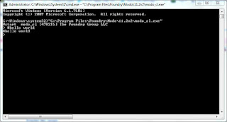
MODO's command line can be accessed from the command line version of MODO and it needs to be run in an administrative cmd window and typing the following...

"C:\Program Files\Foundry\Modo\11.2v2\modo_cl.exe"


Obviously I'm on Windows here but the principles should be the same for Linux and Mac.  However MODO_CL also needs to know about the LDRAW plugin that hopefully you've already installed for the GUI version of MODO - to do this you need to load a config file when you launch MODO_CL so you need to type

"C:\Program Files\Foundry\Modo\11.2v2\modo_cl.exe" -config C:\Users\Neil\AppData\Roaming\Luxology\MODO11.2.CFG

I'm loading the GUI version of MODO's config file (as this config file should know about the LDRAW plugin - assuming you've installed it correctly)


Note that when MODO_CL starts up now it reports "Ldraw plugin done".  This should now allow you to load LDraw ldr files (BUT I had to copy an LDRAW folder to C:\LDraw as this seemed to be the only place MODO_CL would look for the LDRAW files - irrespective of what you have set for your LDRAW location in the GUI version of MODO)

Now you can start to type commands directly into MODO_CL - so this would load my lighthouse2 ldr file...

scene.open "C:\Users\Neil\Google Drive\modoscript\lighthouse2.ldr"


MODO supports a number of scripting languages including python, perl and lua, however initially I just wanted to execute commands directly in the MODO_CL interface as I didn't want to get bogged down having to fend off errors both from the programming language and MODO_CL - if I just executed commands directly in the MODO command line interface then I knew that I would only have to deal with MODO_CL errors. 

You can combine your MODO_CL commands into a simple text file then get MODO_CL to execute each line in the text file in turn - this is a lot easier than having to type each line into MODO_CL individually.

You can load the text file into MODO_CL using the following command 
#"C:\Program Files\Foundry\Modo\11.2v2\modo_cl.exe" -config C:\Users\Neil\AppData\Roaming\Luxology\MODO11.2.CFG < "C:\Users\Neil\Google Drive\modoscript\modo_cl_script.txt"

where modo_cl_script.txt is the name of your script file.

So below is my script to 

Open a LDR file, 
Frame the model in camera (manually) 
Save the file as a MODO native lxo file
Open the lxo file you've just saved
Render the image from the MODO lxo file

I've also included a number of other commands that I tried along the way, discovering that a number of them didn't work in MODO_CL - or though MODO_CL happily tells you that it's executed the command!

#Make sure LDRAW Plugin for Modo is installed
#Currently an LDRAW folder needs to be in C:\LDRAW Modo_CL does not see the LDRAW location set for the plugin in Modo
#But you still need to load the config file so that Modo_CL knows where the LDRAW plug-in is

#CMD LINE...
#"C:\Program Files\Foundry\Modo\11.2v2\modo_cl.exe" -config C:\Users\Neil\AppData\Roaming\Luxology\MODO11.2.CFG < "C:\Users\Neil\Google Drive\modoscript\modoscript04.txt"

#Lots of people have this in their scripts!
log.toConsole true
log.toConsoleRolling true

#Open LDR File
scene.open "C:\Users\Neil\Google Drive\modoscript\lighthouse2.ldr"

#Create a sphere using a built in MODO macro (for testing)
#@"Unit Sphere"


#If you want to directly position the camera in the scene you can use this command (but the numbers x,y,z rotx,roty, rotz will be different for your model!
query sceneservice camera.name ? 0
camera.transformTo Camera -0 0.045 0.280 0 0 0

#If you want to call a seperate python script you can use this - although calling scripts can be tempremental and they may need to live in a specific folder 
#script.implicit "C:\Users\Neil\AppData\Roaming\Luxology\modo_helloworld.py"

#========= Select Items ==========
select.subItem A001dat set mesh;meshInst;camera;light;txtrLocator;backdrop;groupLocator;replicator;surfGen;locator;deform;locdeform;deformGroup;deformMDD2;ABCStreamingDeformer;morphDeform;itemInfluence;genInfluence;deform.push;deform.wrap;softLag;ABCCurvesDeform.sample;ABCdeform.sample;force.root;baseVolume;chanModify;itemModify;meshoperation;chanEffect;defaultShader;defaultShader 0 0

#========= Fit in Viewport ==========
# The tools that you can use in the MODO interface to frame objects do NOT seem to work in the command line - I've included them here for reference
# Select the camera...
#select.subItem camera040 set mesh;meshInst;camera;light;txtrLocator;backdrop;groupLocator;replicator;surfGen;locator;deform;locdeform;deformGroup;deformMDD2;ABCStreamingDeformer;morphDeform;itemInfluence;genInfluence;deform.push;deform.wrap;softLag;ABCCurvesDeform.sample;ABCdeform.sample;force.root;baseVolume;chanModify;itemModify;meshoperation;chanEffect;defaultShader;defaultShader 0 0

#========= NONE OF THE LINES IN THIS SECTION SEEMS TO WORK IN MODO_CL ==========
#viewport.fitSelected 
#camera.fit true true
#camera.syncView
#render.syncView

#========= Save Scene ==========
!scene.saveAs "C:\Users\Neil\Google Drive\modoscript\Lighthouse_saveV01.lxo" $LXOB

#========= If you want to exit the script (before rendering) uncomment the next line ==========
#app.quit

#========= Open scene ==========
# Open the scene you've just saved
scene.open "C:\Users\Neil\Google Drive\modoscript\Lighthouse_saveV01.lxo"
pref.value render.threads auto
#========= Target Camera ==========
#This sort of works but I have not yet worked out how to frame the camera nicely around the model
#select.subItem camera set mesh;meshInst;camera;light;txtrLocator;backdrop;groupLocator;replicator;surfGen;locator;deform;locdeform;deformGroup;deformMDD2;ABCStreamingDeformer;morphDeform;itemInfluence;genInfluence;deform.push;deform.wrap;softLag;ABCCurvesDeform.sample;ABCdeform.sample;force.root;baseVolume;chanModify;itemModify;meshoperation;chanEffect;defaultShader;defaultShader 0 0
#select.subItem mesh001 add mesh;meshInst;camera;light;txtrLocator;backdrop;groupLocator;replicator;surfGen;locator;deform;locdeform;deformGroup;deformMDD2;ABCStreamingDeformer;morphDeform;itemInfluence;genInfluence;deform.push;deform.wrap;softLag;ABCCurvesDeform.sample;ABCdeform.sample;force.root;baseVolume;chanModify;itemModify;meshoperation;chanEffect;defaultShader;defaultShader 0 0
#target set
#========= Or you can move the camera directly after you open the file so frames the object ==========
#camera.transformTo camera -0 0.055 0.090 0 0 0
#========= Start Render ==========
select.Item Render
item.channel step 1
item.channel first 1
item.channel last 1
item.channel outPat "_<FFFF>"
render.res 0 480
render.res 1 270
render.animation "C:\Users\Neil\Google Drive\modoscript\ModoLighthouseScriptRender_v01" PNG

#WORKS!

So what do I get when I run this script...

...the back of my model...doh...more work to do...!


Tuesday 6 March 2018

LDD and BLUERENDER

I've had a very quick look at BlueRender from Eurobricks

http://www.eurobricks.com/forum/index.php?showtopic=109972

As a basic renderer for Lego Digital Designer (LDD) it's pretty good - open your LDD lxf file, and press the big Render button - it then renders your .lxf files into a png image.  This is nice solution for people who are only familiar with LDD and don't want to have to get stuck into the guts of LDRAW and model conversions to create nicer images of Lego.  It seems to render exactly what you see in the LDD interface.


and uses the camera framing from the lxf file and renders all the decals and transparency, lacks some of the rendering finesse of some of the high-end packages but it's a really nice, neat and quick solution for quick LDD renders, which look a lot better than the basic LDD previews.

There is also a simple wireframe preview function so it's fairly easy to create some basic turnarounds - but you need to think about where the center of the model/camera is!


Thursday 1 March 2018

MODO and LDRAW (Part 1)

I've been spending quite a bit of time recently working with The Foundry's MODO and LDRAW.  You can get a 30 day trial of MODO from here: https://www.foundry.com/products/modo  The Foundry have a number of very high end tools that are more often used in feature films, TV and Game creation.  

Previously I've used POV-Ray as my LDRAW renderer.  Given it's age POV-Ray is a fairly good renderer and it's well integrated into the LDAW eco-system, but managing and configuring POV-Ray renders can be fairly challenging and the output can have a bit of "dated" look about it (but that might be just my lack of knowledge of POV-Ray!)   MODO's render quality is incredible "out the box" and surpasses anything that I've achieved to date with POV-Ray.  The MODO interface is a bit of beast but it's still very easy to import LDRAW models and render the images.  The main disadvantage is that you only get 30 days to play with MODO.

LDRAW access to MODO is enabled using Eric Soulvie's excellent MODO plugin - fmtLDraw  https://www.battlefleet.net/fmtldr/   This is donationware so you have to pay something for it, but it's well worth it if you want to create a few stunning renders of your digital Lego models.

This was my test model which features lots of transparency and decals and the render output here is pretty much the default - I just pressed the render button once I'd imported the file.

Here's a few more screengrabs of some of my other models imported into MODO


The only real problem with MODO is that you only get 30 days to test it.   I did email The Foundry, who said you could get a another 30 days with every new release (and there are about 3 releases a year), so you could get 90 days a year otherwise MODO is very expensive after the 30 days are up (whereas POV-Ray is free!)